
Insulation slows heat loss, but it does not add heat. An Industrial Pipe Trace system uses powered heating cable secured to a pipe or tank to offset heat loss and help maintain the required temperature. The right design depends on the line, its operating conditions, and its heat demand.
For commercial and industrial facilities, reliable pipe tracing starts with understanding what the system must protect and how the process operates. This article explains electric trace heating, the role of cable and control selection, and key considerations for pipe-tracing systems in Utah, including Northern Utah and the Wasatch Front.
Key Takeaways
- Understand how electric heating cable helps offset heat loss and maintain a process temperature.
- Learn which pipe and operating conditions inform cable, insulation, sensor, and control selection.
- See how engineering choices shape tracing systems for commercial and industrial piping.
- Explore how controller options can support a facility’s approach to managing heat trace.
What is an electric heat trace system?
Electric trace heating uses powered cable secured to a pipe or tank to offset heat loss. Cable, insulation, sensors, and controls work together to support freeze protection or process temperature maintenance.
Process Temperature Maintenance
On process lines, heat tracing replaces heat lost to the surroundings, helping keep fluid near its required operating temperature. System design accounts for process temperature and pipe heat loss. Sensors measure conditions, while thermostats or process controllers manage cable operation.
Freeze Protection Applications
In cold conditions, exposed or poorly insulated pipes can lose heat and freeze. Trace heating adds heat along the pipe to counter that loss, supporting freeze protection for water lines and other vulnerable services. Design should account for the pipe’s exposure and insulation, not just the facility’s lowest expected temperature.
Insulation and Temperature Hold Time
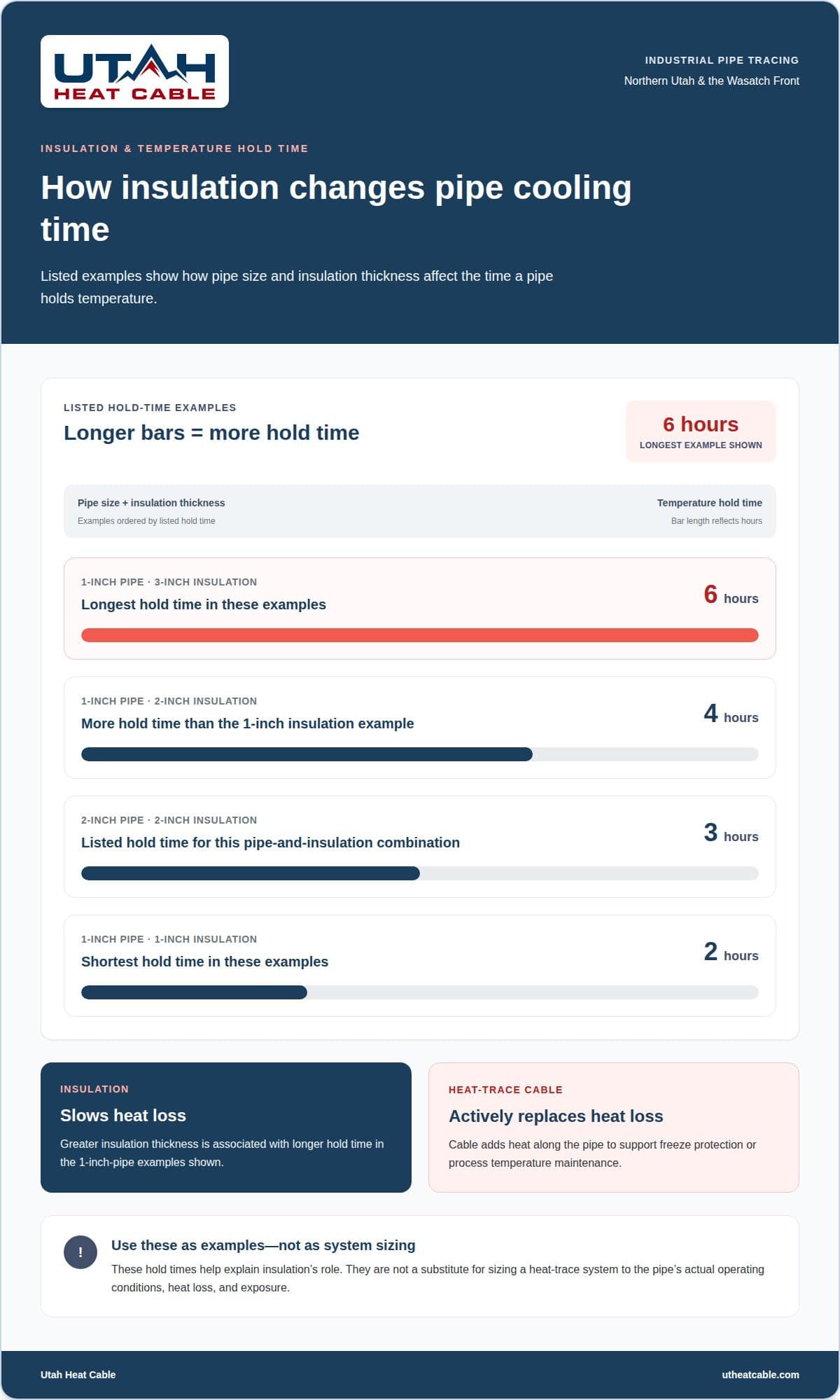
Insulation slows heat loss, while heat-trace cable actively replaces it. Listed temperature hold times show how pipe size and insulation thickness affect cooling: a 1-inch pipe with 1-inch insulation has a 2-hour hold time; with 2-inch insulation, 4 hours; and with 3-inch insulation, 6 hours. A 2-inch pipe with 2-inch insulation has a 3-hour hold time. These examples help explain insulation’s role, but they aren’t a substitute for sizing a system to its actual operating conditions.
Pipe Materials and Ambient Temperatures
Pipe material and ambient temperature both affect heat loss and system performance. The pipe’s thermal behavior, diameter, insulation, and exposure conditions inform cable placement and output. For example, an indoor process line and an outdoor line exposed to cold air have different heat-loss conditions, even if they carry the same fluid. Maintaining temperature properly requires evaluating the complete pipe run and its surroundings.
Heat-trace engineering and system selection
Engineering matches cable, controls, and insulation to the process temperature and pipe route. The right trace system depends on heat loss, electrical supply, and installation conditions.
Inspection and maintenance focus on cable condition, connections, insulation, sensors, and controls. Monitoring can help identify faults that interrupt heat delivery. Troubleshooting follows the system from the power supply through the controls to the heated line.
Installation costs depend on cable type, route length, electrical requirements, controls, insulation, and site conditions. A project quote reflects these factors.
Control and Monitoring Systems
Thermostats or process controllers manage trace-heating temperatures, while sensors provide temperature readings. Industrial systems may also include power distribution and monitoring equipment. If a line loses heat, troubleshoot systematically: check the power supply, controller settings, sensor readings, cable connections, and insulation to locate the interruption before restoring operation.
Fluid and Electric Tracing Systems
Electric heat-trace cables deliver heat along a pipe, with the cable selected for the application. Constant-wattage cables provide uniform heat output along their length; self-regulating cables are another electric option. Fluid tracing, including steam, uses heated fluid as its heat source. Steam systems can deliver two to ten times the heat required, so the process temperature and heat demand matter when comparing approaches.
System Design and Sizing
Design begins with the pipe route and length, process temperature, insulation, and expected heat loss. Engineers use those details to select cable output, power distribution, sensors, and controls. Electrical supply and installation conditions also shape the system. A long-line application may need a different layout from a short process branch, so sizing follows the actual piping arrangement rather than a generic cable choice. Request a heat-trace project quote to discuss the system requirements.
Commercial and industrial pipe tracing
Commercial and industrial tracing must suit the process, piping route, and installation environment. This alignment affects cable placement, heat output, and operation across the full line.
Applicable Codes and Standards
Applicable codes and standards depend on the facility’s electrical design, process, and installation location. In the United States, project specifications and local authority requirements guide which provisions apply. Relevant hazardous-area classifications include zones 1, 2, 21, and 22. Gas groups IIA, IIB, and IIC also inform cable specification. These classifications are selection criteria, not a complete code list. Align electrical plans, piping documents, and site requirements before installation to avoid conflicts.
Installation and Commissioning
Installation starts by mapping each pipe section, fittings, valves, and equipment that need heating. The installer routes cable to maintain contact and account for bends, supports, and heat loss. Valves and flanges may need added cable coverage because their shapes differ from straight piping. For water lines, one described method places cable on the lower half at a 45° angle, secured with tape every 6 inches to 1 foot.
After installation, commissioning checks connections, sensors, control response, and power distribution. Functional checks confirm that the trace system responds to measured temperatures and delivers heat along the piping. Records of cable routes and control settings also support future inspections and troubleshooting by helping identify changes in performance.
Utah Heat Cable
Utah Heat Cable designs and installs heat-trace systems for industrial facilities in Utah, including Northern Utah and the Wasatch Front. Its pipe heat-trace services support freeze protection and industrial temperature maintenance, with controller options to manage system operation. The right design depends on the piping and operating conditions.
Facilities facing winter exposure beyond process piping can also consider Utah Heat Cable’s De-Icing Services, Sidewalk and Driveway Deicing Systems, or Roof Snow Retention. These protect different areas of a property and do not replace pipe-tracing design.
For guidance on cold-weather protection for your facility, contact Utah Heat Cable.
Plan for Reliable Cold-Weather Operations
Before the next cold-weather season, consider how pipe protection fits your facility’s operating priorities. An Industrial Pipe Trace design should support the process while accounting for wider winter needs, from exposed infrastructure to areas affected by ice.
Utah Heat Cable installs Self Regulating Heat Cable and Constant Wattage Heat Cable for heating applications, and provides De-Icing Services for other cold-weather concerns. Discuss your facility’s piping and project requirements with the team to identify an appropriate approach for your site.
A considered plan can help your team prepare with greater clarity and confidence.
Frequently Asked Questions
What is Trace Heating?
Trace heating adds controlled heat along piping or equipment to limit cooling. In a plant, it can help keep process fluid at its required temperature during operation or reduce freezing risk on an exposed line. Electric cable is one method; steam tracing is another. Sensors and controls help match heat delivery to the line’s purpose.
What is industrial pipe tracing and how does it work?
Industrial pipe tracing applies a heat source along a process line to support temperature control or freeze protection. In an electric Industrial Pipe Trace system, heating cable follows the pipe, while sensors and controllers help manage operation. For a long line carrying fluid between process areas, the route and operating conditions inform heat-coverage planning.
What are the main types of industrial pipe tracing systems?
Common options include electric self-regulating and constant-wattage cables, series-resistance and mineral-insulated cable systems, and fluid tracing such as steam. Constant-wattage cable delivers uniform heat along its length; series-resistance cable generates heat through a resistive wire. Mineral-insulated cable has a metal sheath and magnesium oxide insulation. The application determines which system characteristics matter most.
How do electric heat tracing and steam tracing compare?
Electric tracing uses powered cable along the pipe, while steam tracing circulates heated fluid as the heat source. Constant-wattage electric cable provides uniform output along its length. Steam systems can deliver two to ten times the heat required, so it is important to match the heat source to process needs. The choice depends on the application and the facility’s existing infrastructure.
How do you size and select an industrial pipe heat tracing system?
Start by defining the goal: prevent freezing or maintain a process temperature. Then assess pipe material, route length, insulation, ambient conditions, and required temperature. These factors inform cable type, heat output, controls, and electrical needs. For long-line applications, consider the route and heat demand across the full run. Hazardous-area classifications can also affect cable specification.